Friday, July 26, 2013

Selecting screen modes, data decoding methods and palettes

ZX Prism lets you select from a number of different screen data decoding methods. Like the ZX Spectrum, many of these modes use an 'attribute' byte to define the ink and paper colours in each 8x8 square. Like the Timex range of Spectrum compatibles, these modes also support 8x1 attributes. Unlike either range of machines, ZX Prism lets you choose how the attributes are decoded into a logical colour number, and then how that logical colour is translated into the colour which displayed on screen.

Screen resolution and 8x8/8x1 attribute selection is made using 4bit register 0010.
Not all resolutions or features are available for all screen data decode methods. Where a resolution is not available, Prism reverts to 256x192, 8x8 attributes and non-gigascreen*.

OUT 8E3B, 0010xxxx  Screen resolution selection where xxxx is:
 
     0000 – 256x192 8x8 attributes
     0001 – 512x192 (vertically halved display) 8x8 attributes
     0010 – 256x384 (horizontally halved display) 8x8 attributes
     0011 – 512x384 (quartered display) 8x8 attributes
     0100 – 256x192 8x1 attributes (“hicolour”)
     0101 – 512x192 (vertically halved display) 8x1 attributes
     0110 – 256x384 (horizontally halved display) 8x1 attributes
     0111 – 512x384 (quartered display) 8x1 attributes
     1000 – 256x192 Hardware GIGASCREEN 8x8 attributes *
     1001 – 512x192 Hardware GIGASCREEN 8x8 attributes *
     1010 – reserved
     1011 – reserved
     1100 – 256x192 Hardware GIGASCREEN 8x1 attributes *
     1101 – reserved
     1110 – reserved
     1111 – reserved

*Hardware gigascreen is an experimental feature which on even frames interlaces the even lines of screen 0 with odd lines of screen 1 and on odd frames interlaces the odd lines of screen 0 with even lines of screen 1.

Screen data decoding method selection is made using 4bit register 0011:

OUT 8E3B, 0100xxxx  ZX Prism palette selection where xxxx is:
 
     0000 – DEFAULT
          ATTR: D0-D2 ink, D3-D5, paper, D6 bright, D7 Flash

     0001 – 16+16 Colour
          ATTR: D0-D2 ink, D3-D5, paper, D6 ink bright, D7 paper bright

     0010 - 32 Colour
          ATTR: D0-D2 ink, D3-D5, paper, D6 bright, D7 NOT halfbright

     0011 - 16C (4 bits per pixel chunky mode)

     0100 – 256 Colour mode 1
          ATTR: D0-D7 - ink colour, BORDER – paper colour

     0101 – 256 Colour mode 2 - 2 byte attribute read.
          ATTR: D0-D7 - ink colour, D8-D15 - paper colour

     0110 – 16 colour Planar mode

     0111 – [Reserved]
     1000 – [Reserved]
     1001 – [Reserved]
     1010 – [Reserved]
     1011 – [Reserved]
     1100 – [Reserved]
     1101 – Rasterscan (pixel colour = BORDER colour)
     1110 – [Reserved]
 
     1111 – 256 colour chunky (8 bits per pixel) mode

DEFAULT decode mode is just like a ZX Spectrum - Ink and Paper are effectively chosen from two CLUTs of 8 colours each (if the default palette is used, this is identical to choosing colours 0-7 with bright set to either 0 or 1)
 
16+16 Mode is similar to DEFAULT decode mode, except that ink and paper can be selected from a single group of 16 colours (if the default palette is used, this effectively gives you a separate bright bit each for paper and ink)
 
32 Colour mode is similar to DEFAULT decode mode except that ink and paper are both selected from one of four different CLUTs of 8 colours each. If the default palette is used, this effectively gives you 4 levels of bright - the flash bit is an inverse "half-bright" bit (it's "on" when unset, off when set) to prevent the DEFAULT palette being too dark when used in 16 colour modes
.
256(i) colour mode uses the entire attribute byte to dictate the ink colour. Paper colour is dictated by the BORDER colour stored at IO address 0x9E3B.
 
256(ii) colour mode uses two attribute bytes. The first to dictate the ink colour, the second to dictate the paper colour.
 
16 colour planar mode uses 4 256x192 pixel bitplanes to dictate pixel colour. In DEFAULT palette mode this equates to plane 1 (stored in page 5a) being a blue plane, plane 2 (page 7a) being a red plane, plane 3 (page Da) being a green plane and plane 4 (page Fa) being a "bright" plane.
 
256 colour chunky mode uses a byte per pixel. A single screen takes up 48K of VRAM. This mode is only really of use for title (or otherwise static) screens due to the amount of data that needs to be shifted around.
 

There are 3 methods of decoding the "logical colour" into a physical colour:
  • Default palette. This is a hard-coded palette. The first 16 colours are identical to the ZX Spectrum's colours, the next 16 are dimmer versions of the first 16. Colours 0-7 – intensity 1 colours; Colours 8-15 = intensity 3 versions of colours 0-7; Colours 16-23 = intensity 0 versions of colours 0-7; Colours 24-31 = intensity 2 versions of colours 0-7. [The remainder of the default palette are awaiting definition] 
  • Prism palette. This is a user-defined palette. Each colour can be assigned 8 bit red, green and blue elements. Whilst the Prism specification allows 24bit definitions for each colour, some implementations may transcode these into 9bit colour (3 bits per element), 12 bit colour (4 bits per element) etc. My implementation currently uses 12 bit colour (4 bits per element) as shown in the diagrams above
  • GggRrrBb (aka G3R3D2 encoding) is a hard-coded palette as used by ULAplus, MSX etc. Bits 0 and 1 define the blue element; 2,3 and 4 define the red element and 5,6 and 6 define the green element.
Palette selection is made using 4bit register 0100:

OUT 8E3B, 0011xxxx  ZX Prism palette selection where xxxx is:

     0000 – DEFAULT

          Colour 0 – Black, Colour 1 – Blue, Colour 2 – Red, Colour 3 – Magenta
          Colour 4 – Green, Colour 5 – Cyan, Colour 6 – Yellow, Colour 7 – White

            Colours 0-7 – intensity 1 colours (as numbered above)
            Colours 8-15 = intensity 3 versions of colours 0-7
            Colours 16-23 = intensity 0 versions of colours 0-7
            Colours 24-31 = intensity 2 versions of colours 0-7


      0001 – GGGRRRBB

          bit (0) – blue(0)
          bit (1) – blue(1)
          bit (2) – red(0)
          bit (3) – red(1)
          bit (4) – red(2)
          bit (5) – green(0)
          bit (6) – green(1)
          bit(7) – green(2)


     0010 – ZX Prism PALETTE

          Colour 0-255 looked up vs the user-defined ZXPrism Palette


Thursday, July 18, 2013

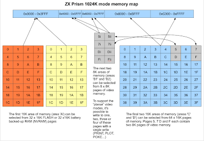
ZX Prism 1024K mode Memory Map


This may go some way to explaining why ZX Prism's codename was "Project Overkill" for a while.

Some further explanation/clarification:

In 1024K mode, the memory page at 0xC000 is chosen using port 0x7FFD in the same way as the 1024K Pentagon (as documented in the ZX Profi documentation by Velesoft):
  • 7FFD bit 0 = Page # bit 0
  • 7FFD bit 1 = Page # bit 1
  • 7FFD bit 2 = Page # bit 2
  • 7FFD bit 6 = Page # bit 3
  • 7FFD bit 7 = Page # bit 4
  • 7FFD bit 5 = Page # bit 5
It should be noted that outside of 1024K mode, port 7FFD bit 5 when true works as expected (ie it locks the current memory configuration and prevents any further memory paging - known as "48K mode" in some circles).

Due to the way this locking works in ZX Prism, enabling 1024K mode from "48K mode" has the effect of re-enabling memory paging.


Wednesday, July 10, 2013

Formal specifications

During the FPGA debugging process, a number of things struck me. First was that I'd made the video RAM interface overly complicated - or at least more complicated than it needed to be - and secondly I realised that whilst I had a lot of notes about how the colour palettes, screen modes and CPU control were going to work, I hadn't sat down and formally produced a full specification.

So I took a couple of steps back and also a small break to brainstorm a feature wishlist. I then thought about how all the different proposed features would work, which I considered "essential" and which were not essential but could be produced easily using the technology required to realise the "essential" features.

As anyone following this blog will be all too aware, this process has taken some time, not least because a number of other areas of my life have been vying for my time as well. It's all for the best though, and the specification boasts a strong and usable feature list.

Here's a taster.

Memory
  • The all-RAM "Special" memory mode available in the Spectrum +2A/B and +3 will be replicated meaning ZX Prism will be able to run the various software that requires it.
  • Outside of the "Special" memory mode, the ROM area (0x0000 - 0x3FFF) is selected from 32 pages of FLASH (512K) or 32 pages of non-volatile RAM. This arrangement is controlled in the same way as the memory in the ZXMMC+ interface, including the fact that the page number selected is affected by the 128K ROM selection bit of port 7FFD. Unlike ZXMMC+, ZXPrism also watches the ROM selection bit of port 1FFD so that 64K rom sets (eg +3 or +3e) can be used. 
  • The memory between 0xC000 and 0xFFFF, is 16K selected from a set of 64 pages, for a total memory of 1MB. The page number is selected in the same way as on the Pentagon, using port 7FFD bits 0-2, 5, 6 and 7.  1MB mode can be disabled for compatibility, re-enabling it can be used to re-enable paging if locked in 48K mode.
  • ZX Prism has 64K of video memory split into 8 x 8K segments. Which segment(s) the video circuitry used depends on which screen data decode method and which screen resolution is selected. As on the Spectrum, the CPU sees video memory between 0x4000 and 0x7FFFx, but unlike the Spectrum, it is possible to choose which 8K segment the CPU sees at 0x4000 and which 8K segment it sees at 0x6000. Of course in BASIC crashes will occur if the segment at 0x6000 is changed, so this is discouraged....
  • To reduce CPU overhead when using one of the "Planar" screen modes, it is possible to tell the hardware that writes to 0x4000 - 0x7FFF write to one, two, three or four planes (segments of video memory) at once.  
Hardware control

ZXPrism hardware control is done via 16 x 4 bit registers. These are modified by writing to IO port 8E3B. The most significant nibble of the data writen to the port selects which register you are writing to, the least significant nibble is the data to be written to the register.

    OUT 8E3B, 0000xxxx - CPU speed control, where xxxx is:

        0000 – Slow (3.5MHz) DEFAULT
        0001 – Double (7MHz) if supported, else 3.5MHz
        0010 – Triple (10.5MHz) if supported, else 7MHz
        0011 – Quadruple speed (14MHz) if supported, else 10.5MHz
        0100 – 6x speed (21MHz) if supported, else 14MHz
        0101 – 8x speed (28 Mhz) if supported, else 21MHz
                                               .  .  .
        1111 – Fastest supported speed (currently 21MHz)


   OUT 8E3B, 0001xxxx - Misc options

        0000 -
        xxx1 - Enable Spectrum 48K style video memory contention
        xx1x - Allow read/write to port xxFF (enable Timex mode)
        x1xx - Enable "Bright Black"
        1xxx - Disable 1024K mode/Enable 48K mode lock

Other hardware control registers will be covered in more detail in future posts:

   OUT 8E3B, 0010xxxx - Screen resolution, attribute size, enable hardware "gigascreen" mode
   OUT 8E3B, 0011xxxx - Screen/Attribute data decode method
   OUT 8E3B, 0100xxxx - Colour decode method (hardcoded, ULAplus palette, PRISM palette)
   OUT 8E3B, 0101xxxx - CPUside Video Memory Control: Planar mode write options
   OUT 8E3B, 01100xxx - CPUside Video Memory Control: segment at 0x4000
   OUT 8E3B, 01101xxx - CPUside Video Memory Control: segment at 0x6000


Hope that wets your whistle - more to come at a later date.